
 Back to Blog
1. Applicable products
- RCbenchmark Series 1580 Thrust Stand and Dynamometer
- RCbenchmark Series 1585 Thrust Stand and Dynamometer
- RCbenchmark Series 1780 Thrust Stand and Dynamometer
2. What describes your problem?
Please find within the following table which describes your problem. Once selected, mark down the troubleshooting points to follow.

3. Problem specific troubleshooting
3.1 Does the product come with the Pitot tube?
Because the pitot tube is very specific to your test environment and wind tunnel, the pressure sensor includes the sensor only and it does not include the pitot tube.
3.2 How to calibrate the pressure probe?
When the air is at rest before a test, you should press the “Tare Airspeed” button that appears under the “Tare load cells” button on the left of the interface.
Our tests show that the sensor has an accuracy of 1% FS when tared but not calibrated. Although not necessary for most applications, you can also calibrate your sensor.
If you are calibrating your sensor, first select the displayed unit of pressure as mm of H2O (or as inch of H2O) in the “Setup tab”. Then go to the “Utilities” tab and connect the sensor as shown below. The blue parts of the drawing are water. You can use a large cup to contain the water. The distance “d” should be precisely measured. We recommend using a “d” of around 50 cm, but not more than 70 cm.
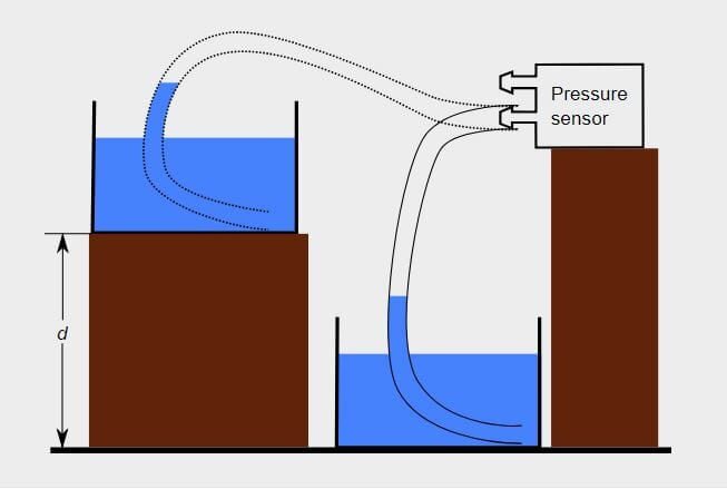
To calibrate the sensor:
- Place the water container with the tube on the lower surface as shown in Fig. 1.
- Press the “Tare airspeed” button.
- Place the water container on the higher surface. The distance d should be about 50 cm (20 inches) to minimize errors.
- Adjust the calibration coefficient until the pressure value matches the height difference “d”.
3.3 How to control incoming air-speed in the wind tunnel?
You may connect your wind tunnel’s ventilator to the Series 1580/1585’s main circuit, or the Series 1780 main board, in order to control the incoming airspeed.
To start, make sure that your fan has a speed control / regulator session and it may be controlled and regulated by a 50 Hz PWM signal. If so, you may then connect the control cable to the Servo port on your Series 1580/1585 main circuit or the Series 1780 Power and Control Console.
See guideline SITPWM - PWM troubleshooting guideline for more information.
4. Problems persist?
We support all issues related to the measurement tools itself, and we can provide limited support regarding your test setup and power-train selection. If you need extended support for your specific tests, manufacturing facility or UAV, contact us at sales@tytorobotics.com. We offer extended support contracts including phone and video conferences at affordable rates.
To obtain a solution to your problem faster, please indicate which troubleshooting steps you have already done. Also, include the debug log from the software. If relevant, please also include a screenshot or pictures of the issue.
4.1 Cross-reference to other types of problem
- SITPWM: refer to this guideline to see how to control through the Servo port.
- SW1SVP: it is also possible to use a script to automatically control the wind tunnel’s ventilator in order to simulate the incoming airflow.