


 Back to Blog
1. Applicable products
- RCbenchmark Series 1520 Thrust Stand
- RCbenchmark Series 1580 Thrust Stand and Dynamometer
- RCbenchmark Series 1585 Thrust Stand and Dynamometer
2. What describes your problem?
Please find the issue which describes your problem best in the following table. Once selected, mark down the troubleshooting points to follow.

3. Problem specific troubleshooting
3.1 I cannot connect the circuit to the PC
- Please confirm the green light on the circuit is ON
- Please confirm that you can see a new COM port appear in the RCbenchmark GUI when you connect the USB cable to the computer.
- Please confirm you use the correct version of the firmware for your board. You can flash the firmware at “Setup” -> “Firmware Upgrade” section. Please select the product you are using now in the drop-down menu then click “Flash Firmware vx.xx” to upgrade the firmware on your board.
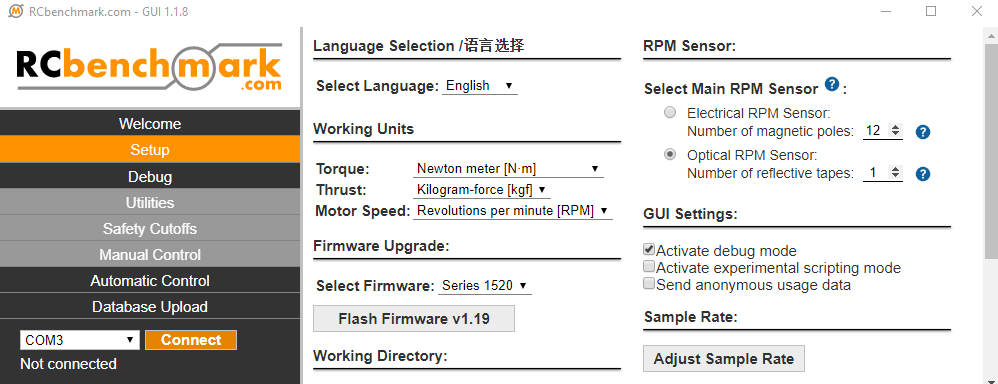
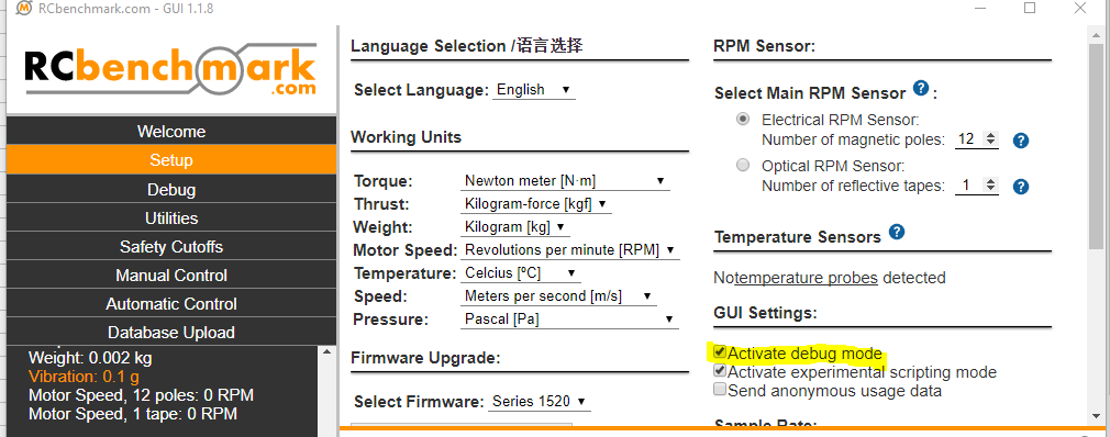
- If the red LED is flashing when you power up the circuit, please send us a screenshot of the “Debug” page on the RCbenchmark GUI. The debug page can be activated in Setup -> GUI Setting -> Activate debug mode.
- Please check the components on the circuit. If you find some damaged components, please take a picture and send it to us, info@rcbenchmark.com, for further troubleshooting.
3.2 I cannot flash the firmware
- Please confirm there is no burnt component on the circuit. That situation would commonly happen if a very high current goes through the measurement circuit. If you find burnt parts on the circuit, please take a picture of the circuit and send it to us at info@rcbenchmark.com for further troubleshooting.
- Please confirm that you can get the COM port number from the GUI. You can try to plug and unplug the USB connector on the PC and look for a new COM port in the COM menu after connecting the USB to your computer.
- Please check the green LED on the circuit and see whether it is on. If the green LED is ON, it means that circuit is powered properly.
- If your problem is not solved after completing the steps above, please contact us with details on your problem, and we will try to help. Please attach the invoice you got when you purchased our products in the email you send to us.
4. Problems persist?
We support all issues related to the measurement tools itself, and we can provide limited support regarding your test setup and power-train selection. If you need extended support for your specific tests, manufacturing facility or UAV, contact us at sales@tytorobotics.com. We offer extended support contracts including phone and video conferences at affordable rates.
To obtain a solution to your problem faster, please indicate which troubleshooting steps you have already done. Also, include the debug log from the software. If relevant, please also include a screenshot or pictures of the issue.
4.1 Cross-reference to other types of problem
- S15CIR: broken connector on the circuit that connects to the load cell
- SW1CMG: you may encounter some troubles connecting the mainboard if you use the Series 1580 and the Series 1780 with the SAME computer and the SAME account.