


 Back to Blog
1. Applicable products
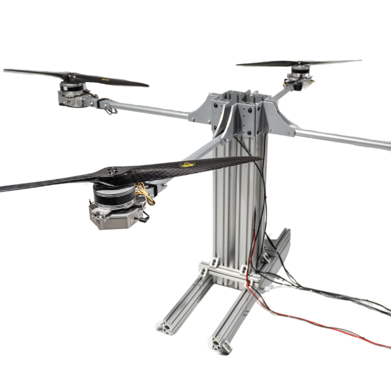
- RCbenchmark Series 1780 Thrust Stand and Dynamometer:
2. What describes your problem?
Please find within the following table which describes your problem. Once selected, mark down the troubleshooting points to follow.

3. Problem specific troubleshooting
3.1 My motor is spinning but I have no RPM reading.
- Confirm the green LED is on when you connect the optical RPM probe on the mainboard.
- If there is no green light on the optical RPM probe, it means that the probe should have been non-functional and you will need a replacement.
- If the green light is on, keep the stand connected to the PC but disconnect it from the power source.
- Go to the SETUP tab and check the box “Activate debug mode”.
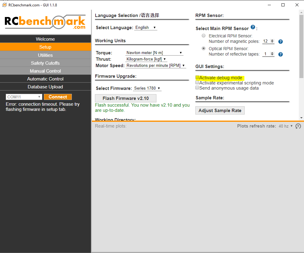
- Once selected, you shall be able to see the DEBUG tab on the left main menu.
- Now connect the mainboard with the thrust stand.
- At the bottom-left of the GUI, you shall be able to see the real-time value of all the measurements including the debug values:

- You can find the optical sensor A/B pin status: 0 or 1 in the debug real-time values
- Make sure that the voltage is below 15 V and then approach the stand. Put a piece of paper or a white tape in front of the sensor on the optical RPM sensor and remove it quickly.
- Check the value at the RPM Pin state on the RCbenchmark GUI.
- If the pin state keeps at 0 or 1 and never changes, you will need an optical RPM probe replacement.
- If you find the value changed, it means the optical RPM probe is functional. Please read section 3.2 to further troubleshoot.
3.2 I think I have a wrong RPM reading.
A wrong RPM reading is hard to observe. But during a test, if you see the motor efficiency hovering over 100%, there is a chance of having a wrong RPM value. In case you find the RPM value fluctuating, see section 3.3.
- Confirm the green LED is on when you connect the optical RPM probe on the mainboard.
- Disconnect the thrust stand from the power source.
- When the voltage drops below 15 V, approach the stand and confirm the logo on the motor is shielded by black tape.
- If the motor casing is made by reflective material, please put a black tape on the rotor and let the sensor on the optical RPM probe face the black tape on the motor.
- The distance e between the motor and the sensor on the optical RPM probe needs to be around 5mm.

- If the motor you are going to test has a large diameter, please put a longer reflective tape on the motor. There are two 2 inches reflective tapes that come with the 1780 optical RPM probe. If you find that the reflective tape is not enough to use, please use a white tape as an alternative.
- Try to manually rotate the motor to see if you receive a correct RPM reading.
- Test again with the motor and ESC.
3.3 My RPM reading is fluctuating
RPM is controlled by the ESC and due to the PWM signal and the PID program within the ESC, the value can be hovering up and down slightly. However, if you observe the RPM fluctuating severely (+/- 2% of the mean value) while you hold the throttle at the same %, you can then use this section to troubleshoot.
- Confirm the green LED is on when you connect the optical RPM probe on the mainboard.
- Run a manual test to hold at a certain throttle and click on Continuous recording, then the software will automatically generate a CSV file.

- Once finished the test, cut the power and disconnect the thrust stand from the power source.
- Approach the stand and confirm the logo on the motor is shielded by black tape.
- If the motor casing is made by reflective material, please put a black tape on the rotor and let the sensor on the optical RPM probe face the black tape on the motor.
- The distance e between the motor and the sensor on the optical RPM probe needs to be around 5mm.
- If the motor you are going to test has a large diameter, please put a longer reflective tape on the motor. There are two 2 inches reflective tapes that come with the 1780 optical RPM probe. If you find that the reflective tape is not enough to use, please use a white tape as an alternative.
- Try again to run a test after finishing the steps above. If the RPM value is still fluctuating, send the CSV file to support@tytorobotics.com and include:
- Subject: S1780 Optical RPM fluctuating
- Your CSV file
- Version of the optical RPM probe (on the PCB)
4. Problems persist?
In general, the optical RPM probe is quite stable. But it may be affected easily by the surface finishing on the rotor of your motor.
We support all issues related to the measurement tools itself, and we can provide limited support regarding your test setup and power-train selection. If you need extended support for your specific tests, manufacturing facility or UAV, contact us at sales@tytorobotics.com. We offer extended support contracts including phone and video conference at affordable rates.
To obtain a solution to your problem faster, please indicate which troubleshooting steps you have already done. Also, include the debug log from the software. If relevant, please also include screenshot or pictures of the issue.
4.1 Cross-reference to other types of problem
- SITMDG: a wrong optical RPM value will lead to wrong motor efficiency
- SW1PID: in case that you are using an automatic script and wish to PID control with an RPM feedback
4.2 Cross-reference from other types of problem
- SITMDG: observation of >100% motor efficiency will require a troubleshooting on the optical RPM probe