


 Back to Blog
Introduction
This article summarizes the research performed at the Sirris Large Climatic Test Facility (Antwerp, Belgium), which looked at drone performance in icing conditions.
The research team included Guillaume Catry, Nicolas Bosson, Luca J. Bardazzi, and Sergio Márquez of Windshape (Switzerland), Özlem Ceyhan and Daniele Brandolisio of OWI-Lab (Belgium) and Flavio Noca of HES-SO University of Applied Sciences and Arts Western Switzerland (Switzerland).

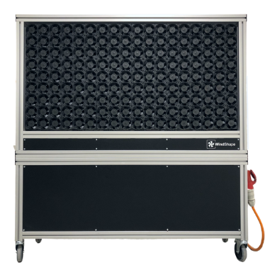
Figure 1: Sirris Large Climatic Test facility
Test Setup
The test setup was designed to characterize drone propulsion system performance as well as ice accretion. It included the following:
- The Sirris Large Climatic Test facility (Antwerp, Belgium) was used to create the temperature and moisture conditions required for icing to occur. The icing test setup is newly-built with 25 water nozzles attached to a gantry crane that cover an area of 6 m x 4 m. The nozzles can achieve a range of droplet sizes by changing the water flow rate so that both glaze ice as well as rime ice can be created.
- A Windshaper wind tunnel was used to generate the apparent wind on the propeller. The system comprises 162 pairs of counter-rotating fan units of 110 W each, evenly distributed over a vertical and flat surface of 1.5 m x 0.75 m. The system is capable of generating wind speeds ranging between 1 m/s and 16 m/s.
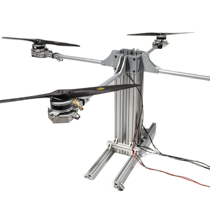
- A Tyto Robotics Series 1585 thrust stand was used to measure propulsion system performance, including thrust up to 50 N, torque up to 2.0 Nm, RPM, power, and efficiency. The load cell is mounted on a robust arm whose angle can be adjusted to vary the propeller pitch angle. The stand’s software platform generates the PWM signal to control the motor. A PID control script was designed by the authors within the software to enable testing at constant motor speed, even when ice grows on the propeller.
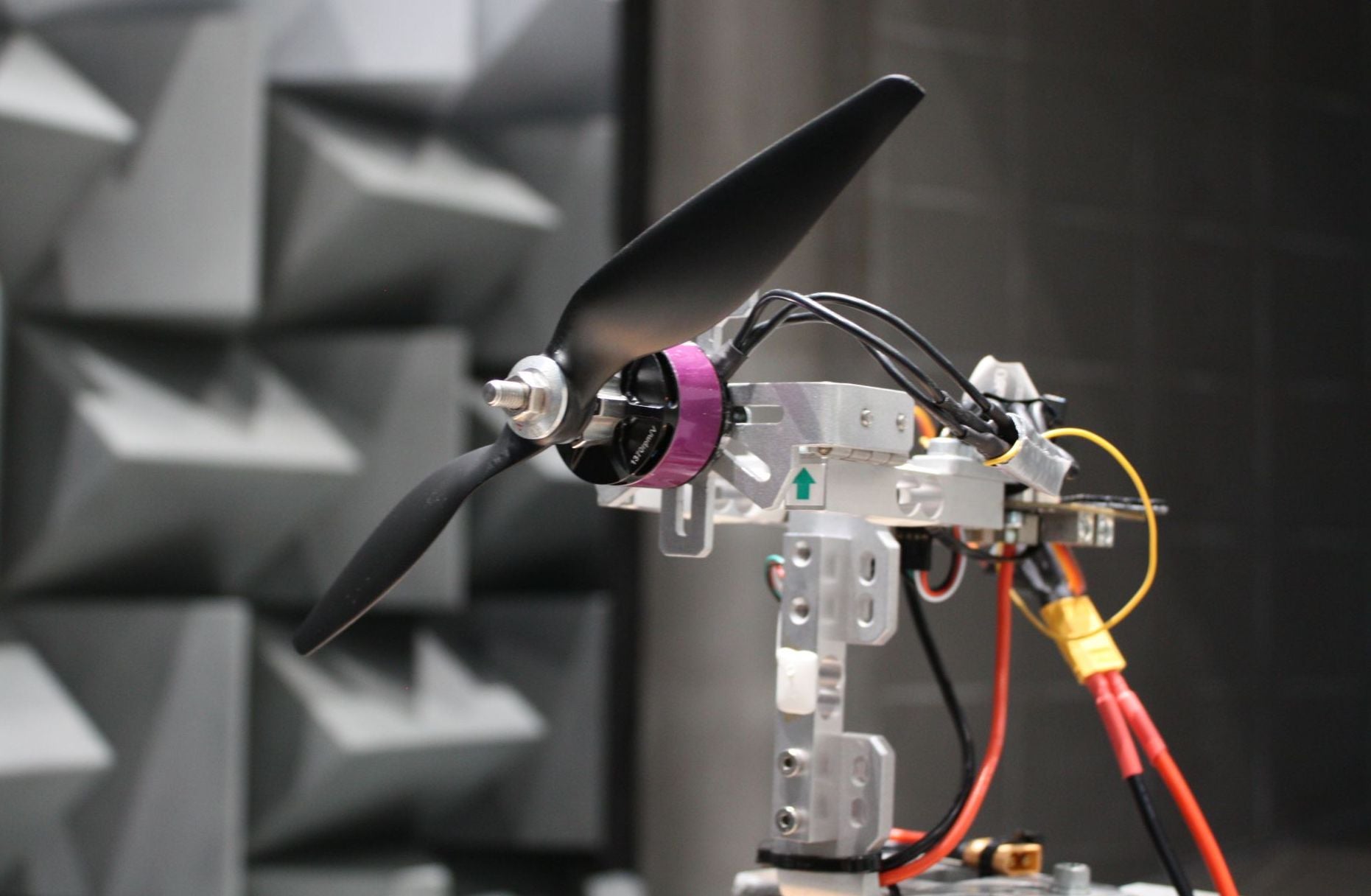
- The brushless DC motor, a Taft Hobby 3553 1550kv, 10 poles, was powered with a 12V laboratory power supply, through a Turnigy 60A SimonK ESC. The propeller was a 3-blade, 9 inch HQProp MacroQuad with a pitch of 5 inches.
- An image capture system was engineered to visualize the formation of ice on the propeller. It featured two short-duration strobe lights that generate flashes as short as 1𝜇s. The flash was triggered by the thrust stand controller based on the motor angular position (RPM sensor), such that the same blade is in the same position in every picture.
- Imaging is performed with a Canon 5D Mk2, a full frame digital SLR camera, set at 6400 ISO, mounted with a 80mm f/1.8 lens set at maximum aperture. During the experiments, a picture is taken every 2s.

Figure 2: The test setup including (1) propeller, (2) test stand for propulsion units, (3) windshaper, (4) water spray, (5) camera, (6) strobe light.
A total of 21 tests were completed using variations of these parameters:
- Propeller speed: 3,500 RPM and 5,000 RPM
- Wind speed: 3.2m/s, 6m/s and 9m/s
- Spray water pressure: 2bar and 8bar
Every test was performed once with a standard propeller, and a second time with a similar propeller covered with anti-ice coating. The temperature was kept at -10°C for all tests.
Results
Ice accumulation on the propeller followed a similar pattern during all tests: ice formation begins after a few seconds of spraying, there is significant ice accumulation by 20 seconds, total loss of propeller thrust occurs around 60 seconds, and shedding of the accumulated ice at around 80 seconds.

Figure 3: Ice accumulation on the propeller
The performance results recorded on the thrust stand (with the coated propeller) revealed several interesting findings:
- Loss of thrust is observed almost immediately after icing conditions are encountered.
- It took just over 1 minute for thrust to decrease from 1.6 N to 0 N.
- When the ice is shed from the propeller around 75 seconds, there is a rapid increase in thrust as the RPM increases before the PID is able to stabilize it.
- The mass of the ice accretion just before shedding was 17 g.
- Propeller efficiency declines gradually as ice accumulates, all the way to 0% just before shedding.
- The propeller with the anti-icing coating maintained thrust >0 N about 4 times longer than the propeller without the anti-icing coating (48 seconds compared to 12 seconds).
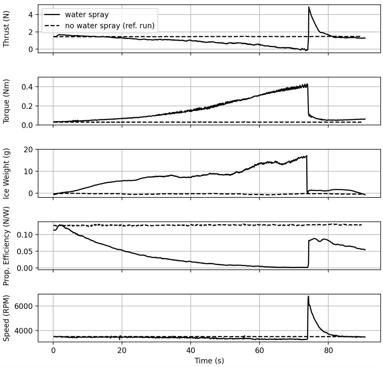
Figure 4: Evolution of the thrust, motor torque, ice weight, propeller efficiency, and motor speed during a test at 3500 RPM with wind speed set to 3.2m/s. The dashed line represents the no-icing control. The solid line represents an icing situation with spray water pressure set to 8 bar.

Figure 5: Performance comparison between a raw propeller and a propeller with anti-icing coating.
Conclusion
In conclusion, the study authors developed a realistic test setup that provides a means to study drone performance in icing conditions.
The full article can be downloaded here.


Leave a comment